Whats inside the files?
The goal now is identifying the maps and data from Renesas chip and 93C66. Winols is a kind of Rolls to manage and edit files. I used it in the past and had to re open it. I won’t speak about it here and won’t provide any link. Just to say that you can download a DEMO version for free and see what’s inside the ECU. I am not a pro of tuning, and not familiar with petrol engines. Most familiar with TDI lol.
Renesas H8/3687
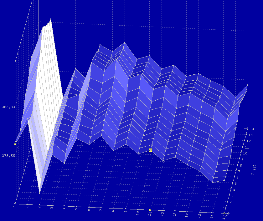
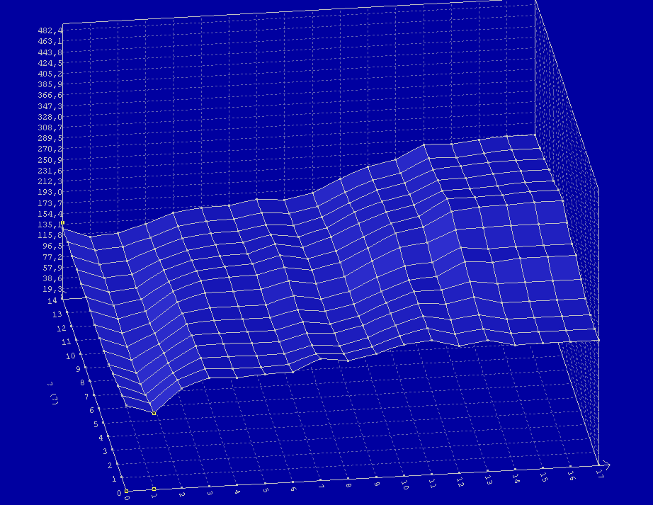
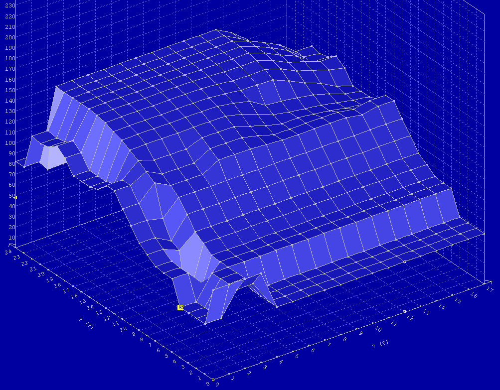
Potential maps list :
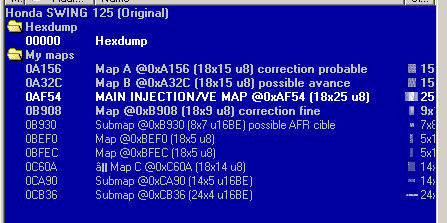
Some of them :

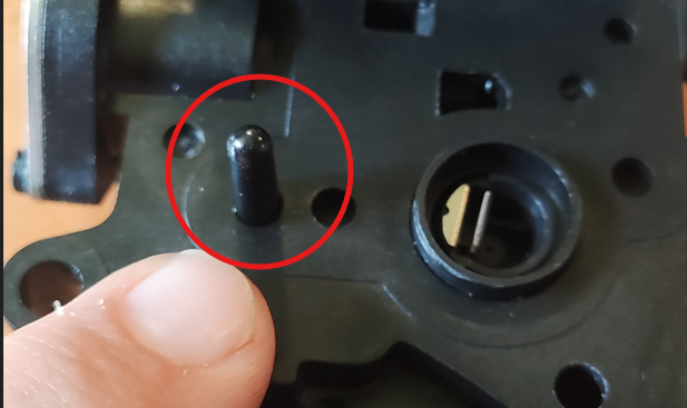
What about IAT sensor?
The IAT sensor is located on the butterfly body side. It is a kind of dark pipe soldered directly on the PCB :
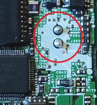
Pins :
The goal is looking where it is connected on the H8 chip, there are multiple ADC channels on B port:
AN0 (ADDRA) → pin 80 (PB0) AN1 (ADDRB) → pin 79 (PB1) AN2 (ADDRC) → pin 78 (PB2) AN3 (ADDRD) → pin 77 (PB3) AN4 → pin 76 (PB4) AN5 → pin 75 (PB5) AN6 → pin 74 (PB6) AN7 → pin 73 (PB7)
Actually my only one CDI (ECU) is used inside the scooter, I will continue this part once i receive another one.
The goal is, to urgently help owners, beeing able to flash the scooter from the diagnostic plug and correcting that.
We have multiple possibilities :
-> disabling DTC -> bad, value will be bad and will generate wrong calculation -> soldering a resistor -> bad for same reason …
My idea is fixing the IAT value to 17° (for exemple) and this will disable DTC. In my region it is the mean temperature of a year.
After some estimations, that will affect the injection at about -3%/+3% which could be really correct to continue using our Swing to go working.
Compared buying a brand new 1640-krj-793 version at about 600 euros plus handwork fees, flashing CPU could spend about the price of the cables so about 30 euros….
How?
To change this part, we won’t go inside map part of the H8 file. We will have to find inside H8 program.
To identify where in the code we need to know where the sensor is connected. We are back to the wait of the new CDI.
Step 1 — Pin → ADC channel → register
The H8/3687 ADC is a single 10-bit converter multiplexed across 8 inputs (AN0…AN7). Each AN
Step 2 — Filter the 77 ADC accesses
I already have a list of every byte in the firmware that reads MOV.B @0xFFAx, R
Step 3 — Distinguish init code from runtime read A few of those hits are setup code (writing to ADCSR to start a conversion). I drop those. What remains are the post-conversion reads of the IAT result. Typically only 2–4 sites survive — and one of them appears in a tight loop or an interrupt handler that runs every few ms. That’s the periodic IAT acquisition routine.
Step 4 — Confirm by following the data flow
After the MOV.B @0xFFA
stored into a RAM cell (e.g. MOV.B R
Step 5 — Write the patch minimal-invasive at that site:
Constant injection — Replace the MOV.B @0xFFA
This is the plan to patch IAT sensor.
That’s the full pipeline: pin → register → 5–15 candidates → 2–4 finalists → 1 patch site → 2–4 byte modification.